Andrew operation and maintenance Specifications
Browse online or download Specifications for Television antennas Andrew operation and maintenance. Andrew operation and maintenance Specifications User Manual
- Page / 42
- Table of contents
- BOOKMARKS
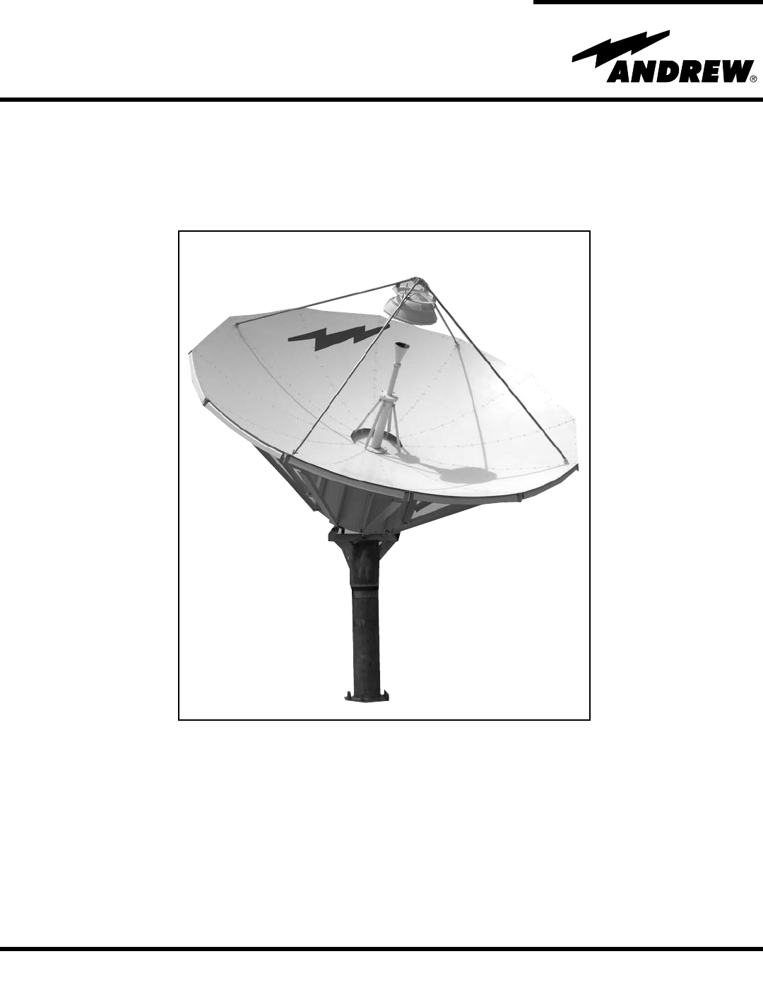
- 4.9-Meter ESA 1
- Table of Contents 2
- Introduction 3
- • Place or change orders 4
- How to Use This Manual 5
- Getting Started 6
- Recommended 7
- Installation Procedures 10
- Foundation 11
- Preparation 11
- Foundation Notes 12
- Reflector/Back 14
- Structure 14
- Assembly 14
- Support Brackets 18
- Subreflector 18
- (Motorized Mount 27
- Reflector to 28
- Ground Mount 28
- IMPORTANT 30
- Operation 33
- Adjustment 37
- Preventive Maintenance 38
- Mechanical Parts 39
- Inspection 39
- Antenna 39
- Lubrication Chart 42
Summary of Contents
Andrew Corporation10500 West 153rd StreetOrland Park, IL U.S.A. 60462Telephone: 708-349-3300FAX (U.S.A.): 1-800-349-5444Internet: http://www.andrew.co
OverviewFoundationPreparation10Installation ProceduresThis section provides installation procedures for the 4.9-Meter Andrew Earth StationAntenna. The
11Installation ProceduresFigure 1bFoundationPreparation
Foundation Notes12Installation Procedures1. Remove all burrs and sharp edges.2. Dimensions apply before plating.3. Interpret drawing per ANSI Y14.5M-1
A325 TensioningStep 1Step 2Step 3Step 4Step 5Step 613During the installation process, there are several references to the A325 hardware ten-sioning pr
Reflector/BackStructureAssemblyStep 114Installation ProceduresUse of A325 hardware eliminates slippage between mating surfaces under high loadingcondi
Step 2Step 315Installation ProceduresLoosely attach 302511 Ribs to 302648 Short Struts as shown in Figure 4. Note: Do notfully tighten hardware at thi
Step 4Step 516Installation ProceduresWhen all 12 rib/strut sets have been loosely assembled, securely tighten all stainlesssteel shoulder bolts first,
17Installation ProceduresStep 6Attach the reflector panels (with skirts) by placing them on the ribs and sliding theminward carefully guiding them unt
SubreflectorSupport BracketsStep 118Installation ProceduresAttach four 206278 lifting tabs across the second and third pairs of reflector seam holesfr
Step 2Step 319Installation ProceduresAttach the four 302518 Subreflector Support Brackets at the 15th (outer most) reflectorpanel hole position from r
IntroductionHow to Use This ManualGetting StartedInstallationProceduresOperationPreventiveMaintenanceTable of Contents2Table of ContentsIntroduction.
Rotating TubeAssemblyStep 1Step 2Step 320Installation ProceduresNote: Applicable feed installation drawings are included with each feed system.Install
21Installation ProceduresPolarization DriveInstallationStep 1Step 2Step 3Attach the Polarization Drive Assembly as shown in Figure 11. Measure and cut
22Installation ProceduresSubreflectorAssemblyStep 1Loosely attach four 302767 Subreflector Struts together with the four 302769 Apex AngleBrackets as
23Installation ProceduresStep 3Install 302514 Subreflector Assembly to the 302768 Subreflector Ring Support Bracketsas shown in Figure 14. Securely ti
Pedestal GroundMount AssemblyPedestalInstallationStep 1Step 224The pedestal mount is an elevation-over-azimuth mount optimized for geostationary satel
Step 325Refer to Figure 16. Using the 6 foot nylon choker under the stinger arm, and the 3 foot chok-er around the elevation pivot tube, lower the ped
Step 4Step 526Level the pedestal plumb within ±0.5° using the leveling nuts provided.Secure pedestal with washer and nuts as shown in Figure 17.Instal
Step 6(Motorized MountOnly)27Installation ProceduresRefer to Figure 17B. Attach Az/El Jack Screw Assemblies and pedestal jack arm topedestal assembly
Reflector toGround MountAssemblyStep 128Installation ProceduresUsing 5/8” shackles, attach four 16 foot chokers provided to reflector lifting lugs. Li
Step 229Installation ProceduresGently lower the reflector assembly into position and attach to elevation pivot lugs using 3/4”hardware as shown in Fig
IntroductionLike all Andrew earth station antennas, the 4.9-Meter Earth Station Antenna provideshigh gain and exceptional pattern characteristics. The
Figure 20SubreflectorInstallation andAdjustmentStep 130Installation ProceduresFailure to conform to the following alignment procedures may result in n
31Installation ProceduresStep 2Step 3Step 4Step 5Reference the appropriate feed installation drawing and install the feed system assembly.Note: The fe
32Installation ProceduresStep 6Step 7Step 8Recheck subreflector centering and height settings.Remove and store 206278 lifting tabs. Replace panel seam
OverviewAcquiring ASatellite33OperationThere are several procedures that may be used to properly acquire the satellite. Andrewrecommends that a spectr
Step 1Step 2Step 3Step 4Step 5Step 634The following steps provide the procedure for acquiring a satellite.Begin by obtaining the correct Az/El pointin
Step 7Step 8Step 935Move the antenna in azimuth to obtain a null, then move ± in elevation to obtain a largepeak signal. If not, move the antenna in t
Step 1036With all 24 transponder signals of approximately equal amplitude appearing on thespectrum analyzer screen determine the specific antenna syst
SubreflectorAdjustment37OperationAfter the satellite has been acquired and testing has taken place with the spectrum ana-lyzer, the subreflector may n
OverviewGeneral CleaningElectrical Parts38Preventive MaintenanceThis section contains periodic preventive maintenance instructions for the 4.9-MeterEa
Mechanical PartsInspectionAntenna 39Clean mechanical parts by first removing dust, dirt, and other loose contaminants with ascraper, stiff brush (bris
Proprietary DataInformation andAssistanceNoticeTechnicalAssistanceThe technical data contained herein is proprietary to Andrew Corporation. It is inte
40• Visually inspect the feed window for dirt and the feed, feed supports, feed window,and reflector for distortion, foreign object damage and environ
Preservation ofComponent PartsAluminum PartsGalvanizedSurfacesLubrication41When preserving the component parts, refer to the following paragraphs in t
42any protective caps and clean off each lubrication fitting prior to injecting fresh grease.The elevation and azimuth jackscrew assemblies are equipp
OverviewContentThe scope of this manual is intended to provide station personnel with the base installa-tion, operation, and maintenance requirements
OverviewWarningsThe installation, operation, and maintenance of the 4.9-Meter Earth Station Antennarequires qualified and experienced personnel. Andre
RecommendedToolsNOTE: Failure to follow an installation procedure could result in damage to equipmentor personal injury.Additional warnings will be di
Parts VerificationReportingEquipment Loss orDamageReporting VisibleLoss or DamageReportingConcealedDamage InventoryEquipmentReceivedAndrew Corporation
ReturningEquipmentStep 1 Step 2 Step 3 Step 4Step 5Andrew Corporation tries to ensure that all items arrive safe and in working order.Occasionally, de
More documents for Television antennas Andrew operation and maintenance


Related products and manuals for Television antennas Andrew operation and maintenance
 (40 pages)
© 2020, manymanuals.com. All rights reserved. | 0.644 s |
 Manymanuals.com
 Manymanuals.de
 Manymanuals.fr
 Manymanuals.it
 Manymanuals.pl
 Manymanuals.cz
 Manymanuals.es
 Manymanuals-pt.com
Comments to this Manuals